
What Is CNC Milling and How Does It Work?

Time:2026-09-14 Author:Sienna
0%

CNC Milling is a computer-controlled process that removes material from a solid workpiece. A rotating cutting tool shapes metal, plastic, or composite materials into precise components. The machine follows programmed coordinates, often called G-code, across three, four, or five axes. It can produce flat faces, slots, pockets, holes, and complex contours.

The market is expanding, but the numbers require caution. Grand View Research estimated the global CNC machine market at approximately USD 88 billion in 2023, while Fortune Business Insights reported a different valuation and forecast. These differences reflect varying definitions, regions, and machine categories. The broader signal remains clear: manufacturers continue investing in automation, repeatability, and connected production. The U.S. National Institute of Standards and Technology also emphasizes measurement, process control, and interoperability as foundations for reliable advanced manufacturing.

Small details matter.

A secure workholding setup, suitable tool geometry, and correct cutting speed can determine whether a part succeeds. Poor chip evacuation may leave scratches inside an aluminum pocket. Excessive tool wear can quietly push dimensions outside tolerance. Manufacturing scholar Serope Kalpakjian described manufacturing as “the transformation of materials into useful products through a variety of processes.” That principle explains CNC Milling well: software directs motion, but engineering judgment controls the result.

This process is not entirely automatic. Operators still select tools, verify offsets, inspect surfaces, and respond to vibration. That human layer is easy to underestimate. This guide explains how CNC Milling works, what happens between the digital model and finished part, and where practical limitations can challenge impressive specifications.
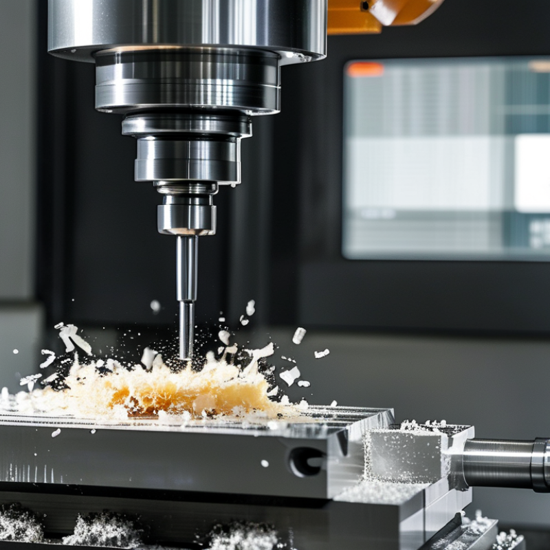
What Is CNC Milling and How Does It Work?

CNC Milling Defined: Machine Components and ISO G-Code Control

What Is CNC Milling and How Does It Work?

CNC milling removes material with rotating cutters controlled by programmed coordinates. A rigid frame supports the spindle, table, axes, and workholding system. Each component affects accuracy. A loose fixture can ruin an otherwise correct program.

The controller reads ISO 6983 G-code, often called standard CNC code. G00 commands rapid movement, while G01 commands controlled linear cutting. G02 and G03 create circular paths. Tool offsets adjust length and diameter errors. Coolant, feed rate, spindle speed, and chip evacuation must match the material.

Small details matter.

The U.S. Census Bureau’s 2022 Annual Survey of Manufactures reported more than 7 trillion dollars in manufacturing shipments. This scale explains why repeatable digital machining matters. UNIDO’s 2024 Industrial Development Report places manufacturing near 16 percent of global economic output, reinforcing the value of reliable production systems.

In practical work, a machinist checks the drawing, clamps the stock, sets the work coordinate, and runs a cautious simulation. The first cut may still reveal vibration or unexpected tool deflection. That is the imperfect part. G-code can be syntactically correct yet operationally wrong. ISO 6983 improves communication, but it does not replace judgment, measurement, or inspection.

How CNC Milling Works: From CAD/CAM Design to Material Removal

What Is CNC Milling and How Does It Work?

How CNC Milling Works: From CAD/CAM Design to Material Removal

CNC milling begins with a three-dimensional CAD model. Engineers define dimensions, tolerances, holes, and surface requirements. CAM software then converts this design into toolpaths. These paths control cutter movement, spindle speed, feed rate, and cutting depth. The result becomes machine-readable G-code. The cut begins.

Before machining, an operator secures the workpiece and checks its material, datum, and tool condition. Probes may locate the stock within a few microns. The machine removes material through controlled rotations and linear movements. Roughing removes most excess metal quickly. Finishing passes create smoother walls and tighter dimensions. Coolant carries away heat and chips. Chip removal matters more than many beginners expect.

A perfect simulation can still lie. Tool deflection, vibration, thermal growth, or incorrect workholding may damage accuracy. Experienced machinists inspect the first part and adjust offsets carefully. ISO 230-2 provides methods for evaluating machine positioning accuracy. Deloitte’s 2024 Smart Manufacturing and Operations Survey found that 86% of manufacturers expect smart manufacturing to support competitiveness within three years. The International Federation of Robotics reported 4.28 million industrial robots operating worldwide in 2023, showing how automation is reshaping production floors. CNC milling remains practical because it links digital instructions with measurable material removal. Even so, software cannot replace judgment at the machine.

What Is CNC Milling and How Does It Work? - How CNC Milling Works: From CAD/CAM Design to Material Removal

Workflow Stage Primary Input How It Works Typical Data or Result
1. Part Concept and CAD Modeling 2D drawing or 3D solid model The part geometry, dimensions, holes, pockets, radii, and datum references are defined in computer-aided design software. A dimensioned digital model used as the manufacturing reference.
2. CAM Process Planning CAD model, stock dimensions, tooling data, and workholding plan CAM software selects machining strategies such as facing, pocketing, contouring, drilling, and finishing. Toolpaths that define cutter movement, cutting depth, step-over, and machining sequence.
3. Toolpath Verification Calculated toolpaths and machine configuration The programmed motion is simulated to identify collisions, excessive cutting depth, gouging, and remaining material. A verified toolpath with fewer risks before machine execution.
4. G-Code Generation Post-processed CAM toolpath A postprocessor converts the toolpath into machine-specific numerical-control instructions, commonly called G-code and M-code. Programmed commands for axis movement, spindle operation, coolant, feeds, and tool changes.
5. Workpiece Setup Raw stock, fixture, cutting tools, and work offset The stock is clamped securely, tools are measured, and the machine coordinate system is aligned with the part datum. A repeatable setup with defined X, Y, and Z work coordinates.
6. Machine Preparation NC program, tooling, coolant, and machine parameters The operator loads the program, confirms tool offsets, checks clearances, and performs a dry run or controlled first move when appropriate. A machine ready to begin cutting under controlled conditions.
7. Material Removal Rotating cutting tool and programmed axis motion A multi-edge cutter removes material through the relative motion of the spindle and workpiece along controlled linear or rotary axes. Features such as faces, slots, pockets, steps, contours, and holes.
8. Roughing Operations Oversized stock and roughing toolpath Larger cutting depths and feed rates are generally used to remove bulk material efficiently while leaving material for finishing. A near-net-shape part with a controlled finishing allowance.
9. Finishing Operations Remaining stock and finishing toolpath Smaller radial and axial cuts are used to achieve final dimensions, surface quality, and profile accuracy. Final surfaces and features that meet the drawing requirements.
10. Cutting-Parameter Control Tool diameter, material, spindle speed, feed rate, and depth of cut The machine controls spindle rotation and feed motion according to calculated cutting conditions. Stable cutting, acceptable chip formation, controlled heat, and predictable tool life.
11. Coolant and Chip Management Coolant method and chip evacuation plan Flood coolant, mist, air blast, or dry cutting may be used according to the material, tool, operation, and machine requirements. Reduced heat buildup, improved chip evacuation, and lower risk of chip recutting.
12. Inspection and Quality Check Finished part, engineering drawing, and measuring equipment Critical dimensions, tolerances, hole locations, surface condition, and visual defects are checked against the design requirements. An accepted part, or documented feedback for toolpath or setup adjustment.
Technical note: Actual spindle speed, feed rate, depth of cut, tolerance, surface finish, and tool life depend on the workpiece material, cutting-tool geometry, machine rigidity, workholding, coolant strategy, and specific machining operation.

CNC Axes Explained: 3-, 4-, and 5-Axis Machining Capabilities

CNC milling converts digital CAD instructions into controlled cutting movements. A spindle removes material while servo motors position the workpiece along programmed axes. The machine does not “understand” design intent; it follows coordinates, tool offsets, speeds, and feeds.

Three-axis milling moves X, Y, and Z. The cutter travels left-right, forward-backward, and vertically. It suits plates, pockets, brackets, and many prismatic parts. However, deep walls may require several setups. Each setup can introduce alignment errors. ISO 230-2 defines methods for checking positioning accuracy and repeatability, which operators should verify rather than assume.

Four-axis machining adds rotation, usually around the X-axis. A cylindrical part can be indexed around its circumference without repeated clamping. This reduces handling time, but indexed motion is not continuous multi-face cutting. Five-axis machining adds another rotary axis, allowing the tool to approach sloped surfaces and complex cavities. Shorter tools can reduce vibration near curved edges. Yet programming, collision checking, and inspection become more demanding.

A 2024 Fortune Business Insights report valued the global CNC machine market at about 83.99 billion dollars in 2023. That growth reflects wider automation, not automatic proof that five-axis is best. In practice, three-axis equipment may deliver better value for simple geometry. Experienced machinists still compare tolerance, fixture cost, tool access, and inspection time. More axes can solve problems. They can also create new ones.

Cutting Parameters: Spindle Speed, Feed Rate, and Depth of Cut

CNC milling removes material with a rotating cutter guided by programmed axes. Cutting parameters control heat, accuracy, tool life, and production time. Spindle speed uses this equation: n = 1000 × Vc ÷ πD. In Machinery’s Handbook, 31st edition, Vc represents cutting speed, while D represents cutter diameter. For a 10 mm cutter at 120 m/min, the result is about 3,820 rpm. Feed rate then follows: Vf = fz × z × n. A four-tooth cutter with 0.04 mm feed per tooth reaches roughly 611 mm/min. The numbers look exact. Real machining rarely does.

Depth of cut needs equal attention. A 2 mm axial cut may suit a rigid setup, but a thin wall can vibrate quickly. ISO 8688-2 recommends controlled cutting tests for comparing tool-life behavior under defined conditions. That matters because speed, feed, and depth interact rather than operate independently. Higher speed can raise temperature sharply. Excessive feed can leave visible marks. I check the first component, listen for chatter, and inspect the chip shape. NIST manufacturing guidance also emphasizes measurement and process verification, not guesswork. I sometimes reduce radial engagement before changing spindle speed; that choice is practical, but not universal. Coolant flow, tool geometry, workpiece hardness, and machine rigidity can overturn handbook values. The starting point is calculated. The final setting is earned on the machine.

Machining Accuracy: Typical Tolerances of Approximately ±0.01 mm

What Is CNC Milling and How Does It Work?

CNC milling removes material with a rotating cutting tool controlled by programmed movements. A digital design becomes toolpaths that guide the tool along several axes. The cutter shapes flat surfaces, pockets, slots, holes, and complex contours. In precision work, typical machining accuracy may reach approximately ±0.01 mm under controlled conditions.

That figure represents a ten-micrometer variation from the specified dimension. It is a target, not an automatic promise. Machine rigidity, tool wear, cutting speed, material stress, and temperature can all affect the result. A warm aluminum part may measure differently after cooling. Small details matter.

Experienced technicians verify critical features with calibrated micrometers, probes, or coordinate measuring equipment. They may machine a test surface, inspect it, and adjust tool compensation before production continues. Fixturing also needs attention. A slightly uneven fixture can distort a thin workpiece and create an error that looks like a programming problem.

Tolerance should match the part’s function. Holding ±0.01 mm across every feature can increase machining time and cost without improving performance. Some parts need tighter control on bearing seats, while other surfaces can accept wider limits. I have found that the first inspection often reveals assumptions missed during design review. Even accurate equipment cannot correct unclear drawings, poor datum choices, or unstable material. Temperature control and regular calibration remain essential for dependable results.

What Is CNC Milling and How Does It Work?

CNC milling uses computer-controlled cutting tools to remove material from a workpiece. The achievable accuracy depends on the machine, material, tooling, fixturing, feature geometry, and inspection method.

Machining accuracy: Typical CNC milling tolerances range from approximately ±0.10 mm for general-purpose work to about ±0.01 mm for carefully controlled high-precision features. These values are representative guidelines rather than universal specifications.

FAQS

What is CNC milling?

CNC milling removes material using programmed cutter movements. A rotating spindle shapes metal or other stock into precise features.

How does a CAD design become a machined part?

Engineers create a three-dimensional CAD model. CAM software converts it into toolpaths, speeds, feeds, depths, and machine-readable G-code.

What happens before cutting begins?

The operator secures the workpiece and checks its material, datum, and tool condition. Probes may locate the stock within a few microns.

What is the difference between roughing and finishing?

Roughing removes most excess material quickly. Finishing passes create smoother walls and closer dimensions.

Why are coolant and chip removal important?

Coolant carries heat away from the cutting zone. Removing chips prevents recutting, surface damage, and possible tool problems.

What can reduce CNC milling accuracy?

Tool deflection, vibration, thermal growth, and poor workholding can shift dimensions. A perfect simulation can still be wrong.

When is three-axis milling suitable?

Three-axis machines move along X, Y, and Z. They suit plates, pockets, brackets, and many prismatic parts.

What do four-axis and five-axis machines add?

Four-axis machining adds rotation for indexed access around cylindrical parts. Five-axis machining reaches sloped surfaces and complex cavities.

Is five-axis machining always the better choice?

No. Three-axis equipment may offer better value for simple geometry. Compare tolerance, fixture cost, tool access, and inspection time.

Can software replace an experienced machinist?

No. Software follows coordinates and offsets, but it cannot fully judge vibration, tool wear, or unexpected workholding problems.

Why should the first machined part be inspected carefully?

The first part can reveal incorrect offsets or alignment errors. Small adjustments may protect later parts from repeating the same mistake.

Conclusion

CNC Milling is a computer-controlled manufacturing process that removes material from a solid workpiece using rotating cutting tools. The machine typically includes a spindle, workholding system, cutting table, drive mechanisms, and a control unit that interprets ISO-standard G-code. Production usually begins with a CAD model, which is converted through CAM software into toolpaths and machining instructions. The machine then follows these programmed movements to shape the material accurately and consistently.

CNC milling machines may operate along three axes for basic cuts, while four- and five-axis systems provide greater access to angled surfaces and complex geometries. Key cutting parameters include spindle speed, feed rate, and depth of cut, all of which must be balanced according to the material, tool, and design requirements. With suitable programming, tooling, and machine calibration, CNC Milling can achieve typical dimensional tolerances of approximately ±0.01 mm, making it suitable for precise components and repeatable production.

Sienna

Sienna

Sienna is a skilled marketing professional with a deep expertise in our company’s core products and services. With a passion for innovation and detail, she plays a pivotal role in crafting insightful blog posts that not only highlight the unique features of our offerings but also provide valuable......