
What Are the Top Types of Rapid Prototyping?

Time:2026-09-24 Author:Aria
0%

Rapid Prototyping turns an early idea into something people can see, touch, test, and challenge. It can reveal a weak hand grip, a confusing screen, or a part that simply does not fit. The process is practical, but it is not automatically efficient. Choosing the wrong method can waste material, time, and valuable feedback.

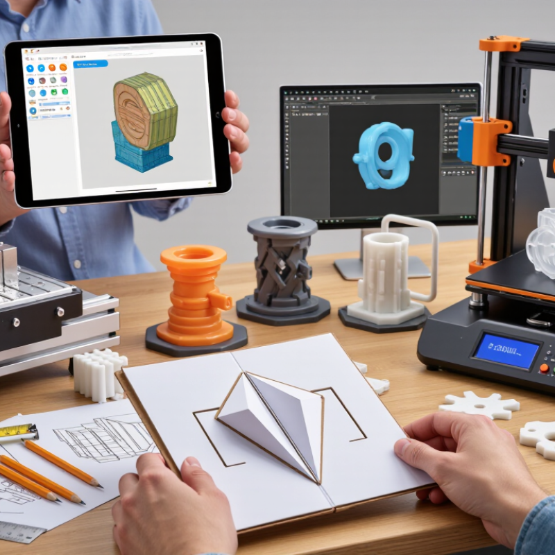
This guide examines the top types of Rapid Prototyping, including paper and cardboard models, digital prototypes, 3D printing, CNC machining, and functional prototypes. Each option serves a different purpose. A paper model may test shape within minutes. An FDM print can check size and assembly. An SLA print can expose fine surface details. CNC machining can provide a stronger, more realistic part, although it usually requires greater cost and preparation.

David Kelley, IDEO founder and a major voice in design innovation, is often credited with saying, “Fail often so you can succeed sooner.” That principle fits prototyping well. A prototype is not a polished product. It is evidence.

It can also mislead.

A smooth prototype may hide poor durability. A realistic render may conceal a difficult manufacturing process. Even expert teams can overvalue appearance and ignore user behavior. This overview therefore considers more than speed. It compares accuracy, materials, cost, scalability, testing value, and typical applications. The goal is not to identify one universally superior method. The better choice depends on what must be learned next.
What Are the Top Types of Rapid Prototyping?

FDM/FFF Prototyping: 100–330 μm Layers for Low-Cost Iteration

FDM/FFF prototyping uses heated thermoplastic filament to build parts layer by layer. Typical layer heights range from 100 to 330 μm. This range supports affordable, quick design iteration. A 100 μm layer can show finer surface detail, while 330 μm layers reduce printing time. In practical workshop testing, a 0.2 mm setting often balances speed, strength, and appearance.

The process works well for enclosures, brackets, ergonomic models, and assembly checks. Printed parts can expose poor clearances before machining begins. However, visible layer lines remain a limitation. Small holes may print undersized, and thin walls can warp near sharp corners. That happened more often than expected in early trials. FDM/FFF is useful, but it is not automatically precise. Designers should test fit with simple samples before producing larger parts.

Tips: Choose 100–160 μm layers for detail and 200–330 μm for faster iteration. Add small chamfers to reduce edge lifting. Keep critical holes vertical when possible. Measure printed features with calipers, then adjust the digital model. Cooling, material behavior, and print orientation can change results, so record each setting. A low-cost prototype still deserves careful inspection.

SLA and DLP Prototyping: 25–100 μm Layers for Fine Detail

SLA and DLP prototyping are strong choices when a part needs fine detail, smooth surfaces, and controlled dimensions. Layer heights commonly range from 25 to 100 μm. Thinner layers reduce visible stepping on curved edges and small lettering. They also increase printing time, resin use, and post-processing effort. The best setting depends on the part, not just the machine.

SLA traces each layer with a focused light source, while DLP projects an entire layer at once. This difference can affect production speed, edge sharpness, and feature consistency. In practical testing, holes, thin walls, and deep cavities need careful orientation. Poor orientation may create support marks or weak sections. Details matter. A 50 μm layer cannot fix an unsuitable resin or inaccurate exposure settings.

Reliable results require calibrated exposure, stable resin temperature, and properly designed supports. After printing, washing and curing must follow a controlled process. Over-curing can soften tiny gaps and change dimensions. Under-curing may leave surfaces tacky or mechanically weak. Small errors compound. The first print is rarely perfect, especially for parts with mixed wall thicknesses. Experienced teams measure critical features after curing and adjust orientation, exposure, or layer height before repeating the build. This evidence-based adjustment is more dependable than selecting the thinnest layer automatically.

SLS and MJF Prototyping: 60–120 μm Layers for Strong Nylon Parts

SLS and MJF prototyping build nylon parts in layers measuring about 60–120 μm. Both processes use powdered material, so complex shapes usually need no support structures. This freedom helps engineers test clips, ducts, housings, and lattice features before investing in tooling. A fresh nylon part often feels slightly grainy rather than glossy. That texture provides useful evidence. It can reveal whether a grip needs more surface area or a sealing face needs machining.

SLS uses a laser to fuse selected powder areas. MJF applies agents before heat fuses each layer. The exact result depends on the machine, material, and layer setting. At finer layers, small edges and shallow details can appear cleaner. Coarser layers may reduce production time. Nylon parts are strong and relatively light, with good resistance to repeated handling. However, strength is not automatic. Thin walls, sharp corners, and poorly designed snap fits can still fail. Nylon also absorbs moisture, so parts should be stored carefully before testing.

A prototype should face real loads, not just look convincing. Check screw bosses, hinge cycles, impact points, and dimensional changes after conditioning. In design reviews, teams sometimes blame the process when a thin feature was simply underdesigned. I have made that mistake too. The 60–120 μm range is not a magic setting. It is a practical starting point that still requires measurement, testing, and occasional revision.

What Are the Top Types of Rapid Prototyping? — SLS and MJF Prototyping: 60–120 μm Layers for Strong Nylon Parts
Process Typical Layer Thickness Common Materials Strength and Part Characteristics Best-Suited Applications Key Considerations
Selective Laser Sintering (SLS) Approximately 60–120 μm, depending on equipment and build settings Nylon powders, commonly PA 11 and PA 12; some systems also process elastomeric powders Produces durable, functional parts with good design freedom. Unsintered powder supports overhangs, so separate support structures are generally unnecessary. Functional prototypes, housings, ducts, brackets, clips, and small-batch end-use parts As-printed surfaces are typically grainy. Powder removal and optional finishing may be needed; dimensional results depend on geometry and process settings.
Multi Jet Fusion (MJF) Often approximately 80 μm; actual values vary by machine and build configuration Commonly PA 12 and other qualified polymer powders Can produce strong, relatively uniform nylon parts with fine detail and consistent results across a build, subject to geometry and process conditions. Functional prototypes, enclosures, connectors, lattice structures, and production-like plastic parts Powder removal is required. Part color and surface finish can vary; dyeing or other finishing may be used to meet appearance requirements.
Fused Deposition Modeling (FDM) Commonly about 100–300 μm Thermoplastics such as PLA, ABS, PETG, and engineering-grade materials on suitable systems Builds parts by depositing roads of material. Strength is directional, with properties often weaker across layer interfaces. Early form-and-fit checks, larger prototypes, fixtures, and low-cost functional parts Visible layer lines are common. Support material or breakaway supports may be needed, and orientation affects strength and finish.
Stereolithography (SLA) Commonly about 25–100 μm Photopolymer resins, including standard, flexible, and specialty formulations Delivers fine detail and smooth surfaces. Mechanical and environmental properties vary considerably by resin. Appearance models, detailed prototypes, patterns, and parts requiring crisp features Requires washing and post-curing. Support marks may need cleanup, and many resins are less suitable for long-term outdoor exposure.
Digital Light Processing (DLP) Commonly about 25–100 μm Photopolymer resins Cures each projected layer, enabling detailed parts; resolution depends on the projector, build area, and orientation. Small, detailed prototypes and batches of compact components Parts require washing and post-curing. Support planning and resin-specific handling remain important.
Binder Jetting Often approximately 80–200 μm, depending on material and system Powders such as sand, metal, or ceramic, paired with a liquid binder Builds parts without melting the powder during printing; final strength depends on the material and any infiltration or sintering steps. Sand-casting patterns and molds, full-color concept models, and selected metal or ceramic workflows Post-processing is frequently essential. Green parts may be fragile before curing, infiltration, or sintering.
Rapid CNC Machining Not layer-based Machinable metals and plastics, including aluminum, steel, and engineering polymers Produces parts from solid stock, with material properties close to the chosen stock when machining and geometry permit. Precision functional prototypes, load-bearing components, and parts requiring specific stock materials Tool access, setup, material waste, and internal geometry can affect cost, lead time, and design feasibility.

CNC Machining: ±0.05 mm Tolerance for Production-Grade Prototypes

CNC machining can produce production-grade prototypes with tolerances around ±0.05 mm when the part geometry, material, and machining setup are suitable. That precision helps teams test mating features, sliding fits, and mounting holes before committing to larger production runs. A machined aluminum bracket, for example, can reveal whether a 6 mm hole aligns with its mating pin under real assembly conditions. Small details matter.

The stated tolerance is a useful target, not a promise for every feature. Thin walls may flex during cutting, while deep pockets and awkward clamping can make dimensions harder to control. Material movement and measurement methods also affect results. In practice, critical dimensions should be identified on the drawing and checked with appropriate measuring tools, such as calibrated calipers or micrometers. Not every surface needs the same precision. Allowing looser tolerances on non-critical areas can reduce machining time without weakening the prototype’s purpose.

CNC parts are especially valuable when a prototype must withstand repeated assembly, load, or contact with other components. They can expose problems that a visual model misses, including tool access, edge clearance, and fastener fit. Still, one prototype cannot represent every production variation. That limitation is easy to overlook. Use test results to refine the design, and confirm critical fits again when the process or material changes.

Selecting a Method by Tolerance, Speed, Materials, and Unit Cost

What Are the Top Types of Rapid Prototyping?

Selecting a method starts with tolerance, not appearance. Stereolithography suits smooth housings and small details, often achieving around ±0.1 mm on compact features. However, resin parts can become brittle under heat or repeated loading. Fused deposition modeling costs less for large concept models. Layer lines remain visible, and dimensional accuracy often depends on build direction. I have seen a slot fit correctly on one face, then fail after rotation. That detail is easy to miss.

Selective laser sintering handles functional nylon parts without support structures. It works well for snap-fits, ducts, and complex internal channels. Surface texture is grainier, but the parts tolerate practical handling better. CNC machining remains the stronger choice when tight tolerances matter. Many workshops target approximately ±0.05 mm, although geometry and inspection equipment change the result. For metal prototypes, machining may cost more initially, yet it can reduce redesign risk.

Speed and unit cost change the decision at different volumes. A single resin model may be ready within a day, while CNC preparation can add programming time. Powder-based printing becomes more attractive when several parts share one build. The Wohlers Report 2024 valued the global additive manufacturing industry at about $20.0 billion in 2023, after 13.5% growth. That growth reflects wider production use, not just visual prototypes. Still, material waste, finishing labor, and failed builds can distort a simple quotation. A cheaper unit is not always cheaper development.

FAQS

What is FDM/FFF prototyping used for?

It builds plastic parts layer by layer with heated filament. It suits enclosures, brackets, ergonomic models, and assembly checks. It is affordable and quick.

Which layer height should I choose for FDM/FFF parts?

Use 100–160 μm for finer details. Choose 200–330 μm when speed matters more. Around 0.2 mm often balances appearance, strength, and time.

What problems can appear in FDM/FFF prototypes?

Layer lines remain visible. Small holes may print undersized, and thin walls can warp near sharp corners. Fit can fail unexpectedly.

How can I improve FDM/FFF dimensional accuracy?

Keep critical holes vertical when possible. Add small chamfers to reduce edge lifting. Measure printed features with calipers, then adjust the model.

When are powder-based nylon prototypes useful?

They suit clips, ducts, housings, snap-fits, and lattice structures. Complex shapes usually need no support structures. The surface feels slightly grainy.

Are nylon prototypes automatically strong?

No. Thin walls, sharp corners, and weak snap-fits can still fail. Test screw bosses, hinges, impact areas, and repeated movements.

How should nylon prototype parts be stored?

Protect them from moisture before testing. Nylon absorbs moisture, which can change its behavior and dimensions. Conditioning should be recorded.

How do I select a prototyping method?

Start with tolerance, loading, material, speed, and unit cost. Resin suits smooth details, filament suits low-cost models, nylon suits functional shapes, and machining suits tighter tolerances.

Is the cheapest prototype always the best choice?

Not always. Finishing labor, wasted material, failed builds, and redesigns can change the real cost. A lower unit price may hide development risk.

What should every prototype test include?

Check clearances, holes, fit, loads, and surface condition. Test simple samples first. Appearance can mislead, and I have trusted it too much before.

Conclusion

Rapid Prototyping offers several practical methods for turning digital designs into functional physical models, with each process suited to different project needs. FDM/FFF uses 100–330 μm layer heights to provide an affordable option for early-stage testing and repeated design adjustments. SLA and DLP achieve finer details with 25–100 μm layers, making them useful for prototypes that require smooth surfaces, small features, and accurate visual representation. For durable nylon components, SLS and MJF typically build parts with 60–120 μm layers and can produce strong, complex geometries without extensive support structures.

CNC machining provides production-grade prototypes with tolerances around ±0.05 mm, making it a strong choice when dimensional accuracy and material performance are critical. Selecting the right method requires balancing tolerance, production speed, material properties, surface quality, design complexity, and unit cost. By comparing these factors against the prototype’s purpose, teams can choose an efficient process for validation, testing, and design refinement.

Aria

Aria

Aria is a dedicated marketing professional with a deep passion for innovative strategies and a keen understanding of our company's product offerings. With a wealth of experience in the industry, Aria excels at crafting engaging content that highlights the unique features and benefits of our......